
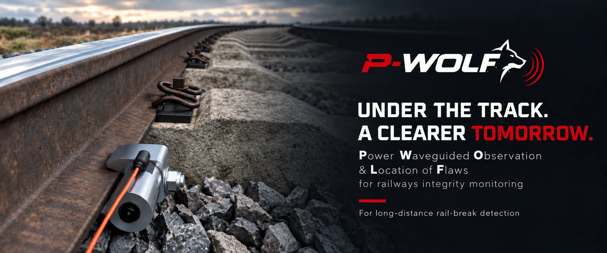
HIGH-POWER GUIDED ULTRASONICS FOR RAIL INTEGRITY
Inject energy.
Read the rail.
A technology platform combining high-power guided ultrasonics, dedicated acoustic sensing and digital signal processing.
Engineered around real hardware. Developing the system architecture to investigate rail breaks and defect-related structural signatures.
THE PRINCIPLE
The rail is also
a waveguide.
A rail carries more than a train. It can also carry elastic waves.
Excitation coupled into the rail travels through different guided-wave modes. A discontinuity can change what comes back, what travels through, and the signature of the received signal.
Follow the signalRead the animation transcript+
- A high-power actuator is positioned at the rail foot.
- An illustrative wave packet travels along the rail.
- A discontinuity modifies the propagating wave.
- A reflected component returns toward the receiving position.
- The demonstration display visualizes the conceptual response.
Timing is slowed for explanation. No measured distance, frequency or detection threshold is represented.
THE COMPLETE ARCHITECTURE
From excitation
to structural signature.
Transmission, propagation and reception form one system. Open a stage to follow the signal.
EXCITATIONShape & amplify+
Programmable bursts, chirps and coded waveforms shape energy in time and frequency. The power stage drives the high-power piezoelectric actuator.
THE RAILCouple & propagate+
The actuator couples energy into the rail foot. Guided-wave modes carry it along the rail, with propagation shaped by the rail profile, supports and coupling conditions.
SENSINGInteract & receive+
Discontinuities can alter reflected and transmitted waves. Dedicated acoustic sensing captures the response independently of the high-power transmitting element.
INFORMATIONProcess & compare+
Correlation, pulse compression and time-frequency analysis help investigate structural signatures. Comparisons must account for temperature, fastenings, welds and coupling effects.
HIGH-POWER EXCITATION
Put energy
into the rail.
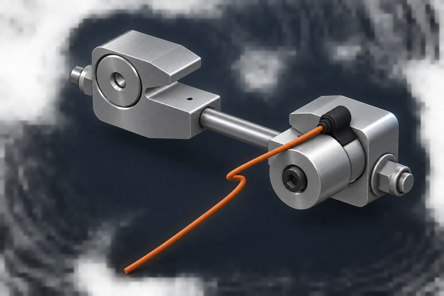
A first high-power piezoelectric actuator has been designed and built.
The Langevin-type architecture is intended for mechanical coupling at the rail foot. The assembly brings the actuation and clamping elements together around the base of the rail.
Energy transfer depends on the complete mechanical interface: geometry, preload, contact conditions and the modes excited in the rail.
P-WOLF is a propagation system,
not simply a pair of ultrasonic probes.
SIGNAL INTELLIGENCE
Power alone
is not enough.
What we transmit, how we listen and how we process the response all influence the information we can recover.
EXCITEProgram the energy.+
Bursts, chirps and coded excitation offer different ways to distribute energy across time and frequency. Broadband investigation can help explore the rail response before an operating strategy is selected.
LISTENSeparate power
from sensitivity.+
Dedicated acoustic-emission and elastic-wave sensing technologies allow reception to be developed around sensitivity, bandwidth and noise performance, independently of the transmitting element.
INTERPRETRecover the signature.+
Correlation, matched filtering and pulse compression are part of the processing strategy, alongside time, frequency and time-frequency analysis of the received response.
MORE THAN AN ECHO
Look for a change
in the rail's response.
A discontinuity may change reflected energy, transmission, arrival time, phase or modal content. A nominal rail response can become a reference for later comparisons.
Fastenings, welds, temperature and environmental conditions can also change the signal. Characterization must distinguish those effects from defect-related changes.
FREQUENCY, MODES & DEFECTS
The right question
is about the mode.
The rail is a complex, dispersive waveguide. Frequency matters, but so do modal shape, energy distribution and the way the track is supported.
INITIAL INVESTIGATION WINDOW
25–35kHz
A region of interest identified in the initial P-WOLF technical study.
A starting point for investigation, not a finalized operating frequency or validated performance specification.
Range is a system property.
Usable range depends on the mode, rail profile, fastenings, coupling, transmitted energy, receiver sensitivity, noise and processing.
Mode selection+
Different modes distribute motion and energy differently across the head, web and foot. Their attenuation and interaction with defects can be different, even at the same frequency.
Excitation & coupling+
A single excitation point may launch several modes. Actuator arrangement and coupling conditions are therefore part of the investigation. Symmetric configurations can be studied to favour selected modal families.
Rail breaks & partial defects+
A complete interruption strongly changes the transmission path. Partial cracks and local section changes may produce weaker reflections, attenuation or mode conversion. Sensitivity and minimum detectable defect size remain to be established for P-WOLF.
Reflected & transmitted waves+
The architecture is intended to investigate reflected-wave responses and transmitter–receiver configurations across a rail section. These are development directions, not claims of validated P-WOLF range.
The real track environment+
Rail supports, ballast, welds, temperature and coupling repeatability all influence propagation and reception. Representative railway conditions must be included in system characterization.
DEVELOPMENT STATUS
Real hardware.
System-level development.
P-WOLF has moved beyond the concept stage. The next step is to turn its building blocks into a characterized architecture under representative rail conditions.
ENGINEERED BUILDING BLOCKSWhat exists today.+
- A first high-power piezoelectric actuator.
- A mechanical concept for rail-foot coupling.
- Dedicated acoustic-emission sensing technologies.
SYSTEM CHARACTERIZATIONWhat comes next.+
- Coupling efficiency and guided-wave modes.
- Signal-to-noise ratio and repeatability.
- Propagation and defect-related signatures.
- Validation in representative track conditions.
P-WOLF is a technology platform under development. System range, detection thresholds and continuous field-monitoring performance have not yet been established.
RESEARCH FOUNDATION
Established physics.
A new system architecture.
Published railway studies document kilometre-scale propagation for selected guided-wave modes. That provides a physical foundation for investigation.
Those results belong to the cited research. P-WOLF range and detection performance require their own characterization and validation.
Guided waves for broken-rail monitoring
Rail-mode selection, excitation and long-distance propagation in published research.
Study on monitoring broken rails of heavy haul railway based on ultrasonic guided waveChirp excitation of ultrasonic guided waves
Broadband investigation and extraction of narrowband responses through processing.
Pulse compression and mode discrimination
Coded excitation and dispersion compensation for analysis in multimodal conditions.
Wave Mode Discrimination of Coded Ultrasonic Guided Waves Using Two-Dimensional Compressed Pulse AnalysisTHE NEXT CONVERSATION
From guided-wave physics
to track validation.
We are interested in technical collaborations, test sections and validation scenarios to investigate propagation, usable range, repeatability and structural discontinuities.
For infrastructure managers, railway specialists, NDT teams and industrial partners.
Talk to Elfi R&D.
Tell us about your rail profile, available test section and the structural discontinuities you want to investigate.
Discuss a validation project